|
One of
the nicest things about a cottage is that it becomes
a place for friends and family to gather and share
memories. But the cherished kind of memory probably
doesn’t include the sound of Uncle Bob’s snoring, or
having to step over half a dozen nieces and nephews
on your way to a midnight snack. With a bunkie, you
can invite overnight guests and still have some
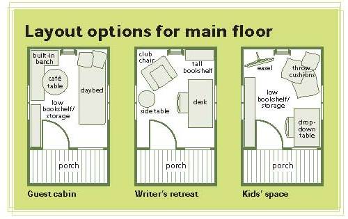
privacy at bedtime. And our Bunkie not only makes an
ideal guest cabin for cottage overflow, it also
doubles as a quiet retreat for those days when even
two’s a crowd (see “Layout Options For Main Floor,”
below).
When we designed this structure, we envisioned it as
suitable accommodation for a couple of adults and
three to four kids. A futon on the main level would
work well for a bed for the big folks, while cots or
an inflatable bed in the loft would be suitable for
the little ones. (Since a queen-size mattress will
fit, a couple of adults can also sleep comfortably
in the loft).
Our local building code requires a building permit
for any structure with floor space greater than 108
sq. ft. This bunkie was designed with that stricture
in mind: At 8' by 13'6", it is exactly 108 sq. ft.
and therefore, in most jurisdictions, does not need
that particular documentation. But check first: Some
municipalities require permits for anything over 100
sq. ft. Cottagers in those areas could modify the
plans – say, by reducing the length to 12'6" – to
fit the more restrictive rules. Even if a building
permit is not required, you must still check with
your local municipality and comply with zoning
bylaws (such as lot line and shoreline setbacks).
This is a big project, but not a very complex one.
In fact, if you built our
free outhouse plans, you will find this to be no
more challenging.
|
Materials List |
MATERIALS
PRESSURE TREATED LUMBER
16 at 2 x 6 by 8'
5 at 2 x 6 by 14'
SPRUCE LUMBER
6 at 1 x 3 by 8'
26 at 2 x 4 by 14'
12 at 2 x 4 by 10'
40 at 2 x 4 by 8'
11 at 2 x 6 by 8'
CEDAR
1 at 2 x 6 by 6'
2 at 6 x 6 by 12'
1 at 6 x 6 by 8'
1 at 4 x 4 by 8'
1 at 2 x 4 by 14'
1 at 2 x 4 by 12'
1 at 2 x 4 by 8'
2 at 1 x 6 by 8'
26 at 2 x 2 by 36"
70 lin.ft. 5⁄4 x 6" deck boards
PINE LUMBER
400 linear feet 1 x 10 rough-sawn pine
230 linear feet 1 x 6 T&G flooring
4 at 1 x 6 by 16'
8 at 1 x 6 by 8'
1 at 1 x 6 by 10'
4 at 2 x 4 by 12'
1 at 2 x 4 by 14'
1 at 2 x 4 by 8'
2 at 1 x 4 by 8'
2 at 1 x 3 by 10'
6 at 1 x 2 by 8'
PLYWOOD
3 at 5⁄8" x 4' x 8' T&G
LP CANEXEL SHIPLAP PANELS
11 at 7⁄16" x 4' x 8'
VICWEST SUPERVIC PROFILE STEEL ROOFING
14 at 30" x 93"
2 x 10' steel roofing ridge cap |
HARDWARE
1 bundle cedar shims (full size)
1 container outdoor glue
250 #9 x 31⁄2" deck screws
250 #8 x 2" deck screws
2 at 3⁄8" x 4" carriage bolts, nuts, and
washers
4 at 5⁄16" x 4" carriage bolts, nuts, and
washers
2 Anderson model 2N1630 double casement
windows
1 Anderson model N1624 casement window (RH)
1 Anderson model W2430 casement window (RH)
1 at 32" x 80" screen door and hardware
1 at 32" x 80" prehung pine entrance door
and hardware
4 at 3⁄8" x 6" carriage bolts, nuts, and
washers
2 at 5⁄16" x 8" lag bolts and washers
2 at 5⁄16" x 6" lag bolts and washers
100 #10 x 31⁄2" wood screws
20 #12 x 31⁄2" wood screws
1' medium link chain
2 quick links
1 brass snap
1 at 3⁄8" x 5" lagged eye bolt
1 at 3⁄8" x 5" threaded eye bolt,
nut, and washer
2 at 21⁄2" butt hinges
1 magnetic catch
2 lbs. of 2"galvanized nails for
Canexel panel
1 box of 11⁄2" screws for steel roof
1 roll VicWest underlayment
1 tube clear silicone caulk
2 tubes acrylic caulk (colour matched)
Foam screened insert for ridgecap |
|
Parts List |
|
Use |
Material |
Type |
|
FLOOR |
|
Joists and end
stringers |
16 at 2 x 6 by
8' |
PT |
|
Stringers and
solid bridging |
5 at 2 x 6 by
14' |
PT |
|
Bunkie floor |
2.5 at 5⁄8" x 4'
x 8' T&G |
PLY |
|
SIDE WALLS |
|
Posts and
headers |
2 at 6 x 6 by
12' |
CD |
|
Top and bottom
plates and blocking |
8 at 2 x 4 by
10' |
SP |
|
Studs (2 per 14'
piece) |
16 at 2 x 4 by
14' |
SP |
|
Bracing |
4 at 1 x 3 by 8' |
SP |
|
Window headers
(doubled) |
2 at 2 x 6 by 8' |
SP |
|
Canexel Shiplap
Panel |
5 at 7⁄16" x 4 x
8 |
PLY |
|
FRONT AND REAR
WALLS |
|
Studs (2 per 14'
length) |
9 at 2 x 4 by
14' |
SP |
|
Top and bottom
plates, wall blocking, and nailing edge |
10 at 2 x 4 by
8' |
SP |
|
Canexel
Shiplap Panel |
6 at 7⁄16" x 4 x
8 |
PLY |
|
PORCH/RAILINGS |
|
Header |
1 at 6 x 6 by 8' |
CD |
|
Newel posts |
1 at 4 x 4 by 8' |
CD |
|
Hand rails |
1 at 2 x 4 by
14' |
CD |
|
Hand rails |
1 at 2 x 4 by 8' |
CD |
|
Pickets |
26 at 2 x 2 by
36" |
CD |
|
Corner brackets |
1 at 2 x 4 by
12' |
CD |
|
Curved pieces |
1 at 2 x 6 by 6' |
CD |
|
Top plate |
1 at 2 x 6 by 8' |
SP |
|
2 x 4 nailing
edge |
1 at 2 x 4 by 8' |
SP |
|
Porch floor |
70 lin.ft. 5/4 x
6 |
CD |
|
Porch ceiling |
70 lin.ft. 1 x 6
T&G |
PN |
|
Trim (ripped to
1 x 2 and routered) |
1 at 1 x 6 by 8' |
CD |
|
LOFT |
|
Joists and solid
bridging |
8 at 2 x 6 by 8' |
SP |
|
Flooring |
150 lin.ft. 1 x
6 T&G |
PN |
|
Gate |
1 at 2 x 4 by 8' |
PN |
|
Lost Railings |
2 at 2 x 4 by
12' |
PN |
|
Panels in gate
and railings |
2 at 1 x 4 by 8' |
PN |
|
Railing shoe and
top rail |
2 at 1 x 2 by 8' |
PN |
|
ROOF AND GABLE
ENDS |
|
Rafters, 22 with
bird’s mouth, 4 without |
26 at 2 x 4 by
8' |
SP |
|
Gable framing |
4 at 2 x 4 by
10' |
SP |
|
Roof boards |
400 lin.ft. 1 x
10 |
PN |
|
VicWestSuper
Vic Profile |
14 at 30" x 93" |
ST |
|
Ridge cap |
2 at 10' |
ST |
|
LADDER |
|
Stringers and
ladder brackets |
2 at 2 x 4 by
12' |
PN |
|
Rungs |
1 at 2 x 4 by
14' |
PN |
|
Railings |
2 at 1 x 3 by
10' |
PN |
|
TRIM |
|
Fascia |
4 at 1 x 6 by
16' |
PN |
|
Corner trim |
8 at 1 x 6 by 8' |
PN |
|
Horizontal
lintel on rear wall |
1 at 1 x 6 by
10' |
PN |
|
Gable end trim |
4 at 1 x 2 by 8' |
PN |
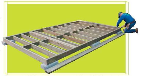
FLOOR
Footings (six in all) will need to be in place
before construction can begin. I am partial to a
double rim joist at the base of structures like this
because of its greater strength, especially at
interlocking corners. And I like pressure-treated
(PT) lumber for any part of a structure close to the
ground – although, since the floor frame does not,
in fact, touch the ground, you could use ordinary
lumber.
|
Free
Wood Cabin Plans
(Right Click on Image, and Select View as
Image or Save As to See the FULL SIZE
Picture)
|
1.
With the parts list (below) and Figures 1 and 2 to
guide you, cut all pieces for the floor frame to
length (wear a dust mask when you cut PT lumber) and
treat the cut ends. Lay out the joist locations –
16" on center – on the inner rim joists. Note that
the measurement to the center of the first joist
from the end must take into account the 3" thickness
of the double rim). Leave a 3⁄4" space between the
two laminated bunkie joists that sit at the 10' mark
and the first deck joist. This gap allows rain and
melt-water to drain between the boards.
2. Nail or screw the inner frame together. (The
3-1⁄2" deck screws in the hardware list are needed
only if you are screwing the frame together.)
Remember to keep joist crowns up; the crown is the
convex edge of a board when viewed from the end.
Nail or screw the outer rim joists to the inner
frame.
3. Cut bridging pieces to length and install between
floor joists.
Tip: When you measure for the bridging, take your
measurements between the joists where they are
secured to the rim, not in the middle. After
installing two or three bridging pieces, check the
cumulative measurement of bridging and joists and
compare with the measure at the rim joist to be sure
you’re not bending the joists out of line. Adjust
the next piece you install to compensate, if needed.
4. Two-and-a-half sheets of 5⁄8" tongue-and-groove
plywood are required to cover the floor for the
dwelling part of the building. Square up the floor –
diagonals must be equal – and screw the plywood to
the floor frame.
5. Level the floor frame, if required.
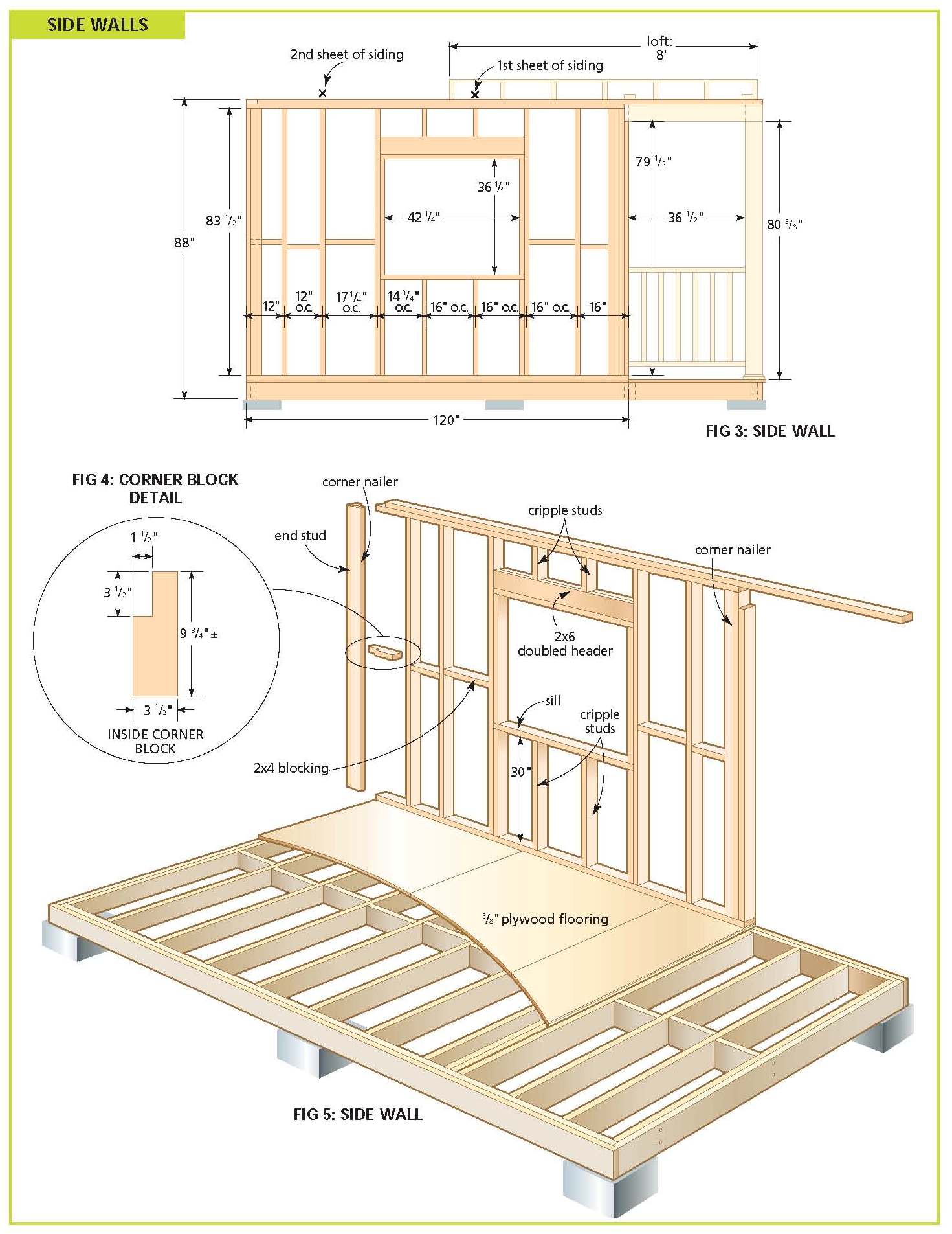
SIDE WALLS
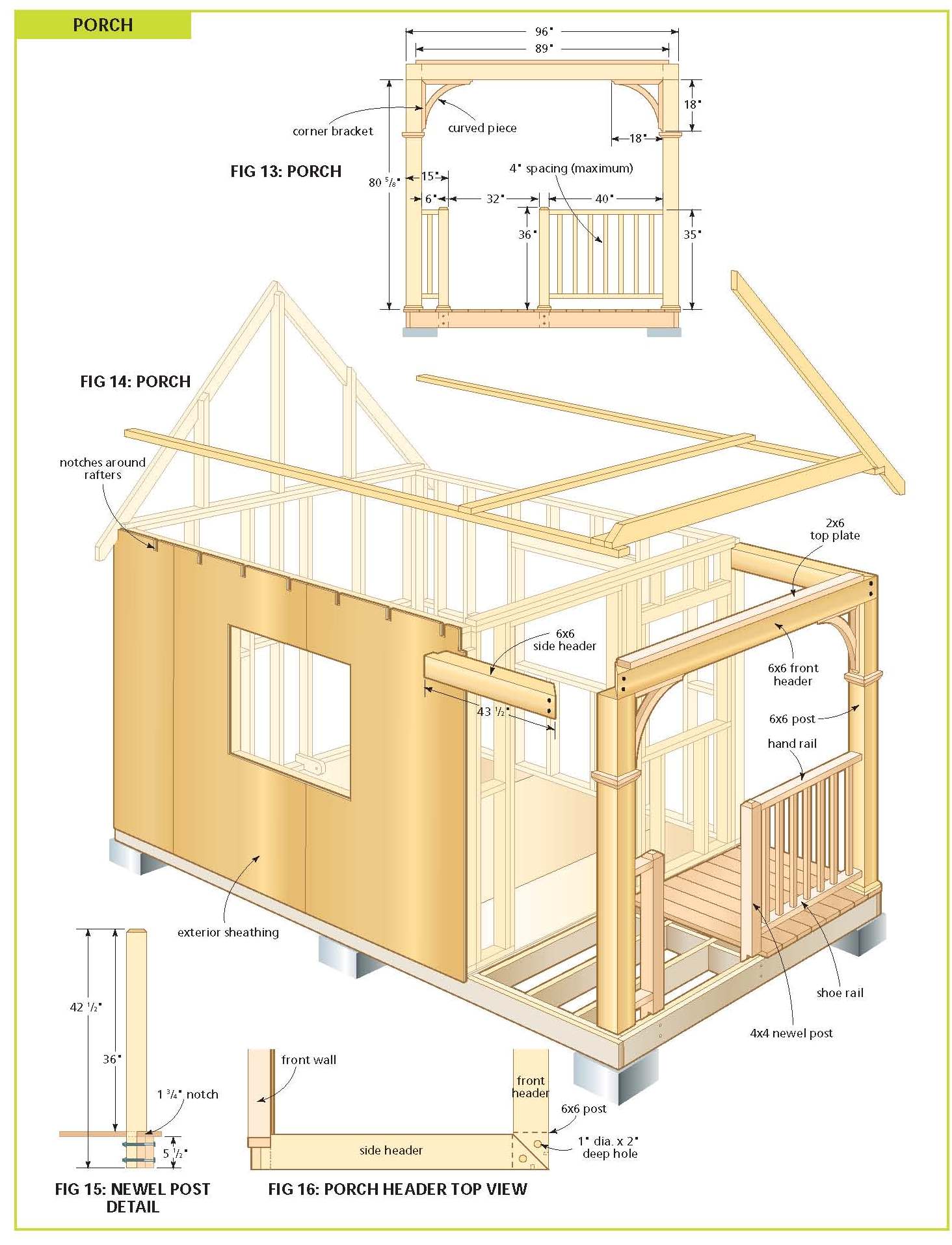
1. Cut the side wall pieces to length. Note that the
window headers consist of two 2 x 6s laminated
together with a piece of 1⁄2" plywood between as a
spacer. Also, the 6 x 6 by 43-1⁄2" side headers are
miterd 45° at the porch end and notched at the other
end (Figures 14 and 16). Drill two 1⁄2" holes –
preferably with a Forstner bit – in the face of each
side header, as in Figure 14. Drill clearance holes.
Cut eight 1⁄2" plugs and put them aside for now. (A
plug cutter is an inexpensive accessory available at
any lumber or hardware store. Use it to make your
own matching plugs from castoffs. Of course, there
are also commercially available plastic plugs.)
2. Lay out the stud locations on the bottom and top
plates as in Figure 3 (make sure that your layout is
consistent with the rough opening for your windows).
Note also that the centers are not all 16". When
siding, start from the porch end. The edge of the
second 4 x 8 sheet will line up with the middle of a
stud marked with an X. The remaining piece is 2'
wide (a 4 x 8 sheet ripped in half provides the 2'
pieces).
3. Nail or screw the wall frame together on the
ground, adding the double top plate last (lay out
the location of the rafters on the double top plate
first, starting from the porch end). Do not add the
6 x 6 side headers yet.
4. Cut the 2 x 4 blocking to length and nail between
the studs.
5. We selected Canexel 4 x 8 pre-finished panels for
this project for a number of reasons: sub-sheathing
is unnecessary, siding time is reduced, and they
look good. On the downside, there is a limited color
selection and the finish is only under warranty for
five years, so repainting could be necessary after
that. Cut five sheets to a length of 931⁄2"
(good-side down to avoid chipping on that side). Rip
one piece in half, lengthways.
6. Lay the sheets on the wall so that the edges meet
the top plate. Transfer the location of the rafters
on the edges of the sheathing. Remove the siding and
cut 11⁄2" by 53⁄4" notches where marked (see Figure
14). The siding panels will sit proud of the top
plate. These notches allow the rafters to sit tight
against the plates and also let the siding butt
against the bottom of the roof boards thereby
sealing the building from drafts. You can be a
little generous with the cuts as small gaps can be
filled with caulking.
7. Lay the siding pieces back on the walls, making
sure that the bottom edges are 3" below the bottom
plates (this lip can later be nailed to the rim
joist). Square up the frame and nail the siding to
the wall using 2" galvanized ardox nails, spaced
about 8" apart.
|
Free
Wood Cabin Plans
(Right Click on Image, and Select View as
Image or Save As to See the FULL SIZE
Picture)
|
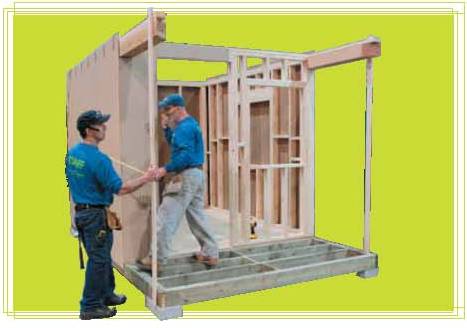
8. Find
two helpers. Stand each wall up in turn, being
careful not to damage the bottom edge of the panels.
Line up the bottom plates with the floor’s edges.
Screw or nail the bottom plates to the floor. Tip:
Don’t drive the nails home yet in case you need to
move the wall. Nail temporary braces from the end
studs to the rim joist. The walls should tip out
slightly at the top.
9. Add a 1 x 3 temporary, vertical brace at the
porch end (see photo), from the rim joist to the end
of each top plate. Insert the 6 x 6 side headers
into the space created when you framed the side
walls. Screw to the top plates and to the 2 x 4
studs. This is also a helper-assisted procedure!
through the top plate and into the side header where
indicated in Figure 16.
10. Drill a 1"-dia. by 2"-deep hole down through the
top plate and into the side header where indicated
in Figure 16. Drill a 5⁄16" clearance hole all
the way through.
11. If you have a reciprocating saw, cut out the
window openings from the inside. If you only have a
jig saw, drill holes through the paneling at each
corner, go outside, draw lines between the outside
radii of the holes, and follow the lines to cut out
the window openings.
12. Do not add the 6 x 6 posts yet.
|
Free
Wood Cabin Plans
(Right Click on Image, and Select View as
Image or Save As to See the FULL SIZE
Picture)
|
REAR
WALL
1. Cut all the pieces and assemble the rear wall as
shown in Figures 8 and 9. Since there are no window
openings, cladding is simply a matter of nailing the
two 4' by 89" panels to the assembled wall. Make
sure that the top edges of the panels are lined up
with the bottom edge of the top plate, i.e., between
the two plates.
2. With a helper, lift the rear wall assembly into
place. Nail or screw the bottom plate to the floor.
Nail or screw the corners together. Nail the 3-1⁄2"
overhangs to the side wall end studs. Nail the
bottom edge of each panel to the rim joists.
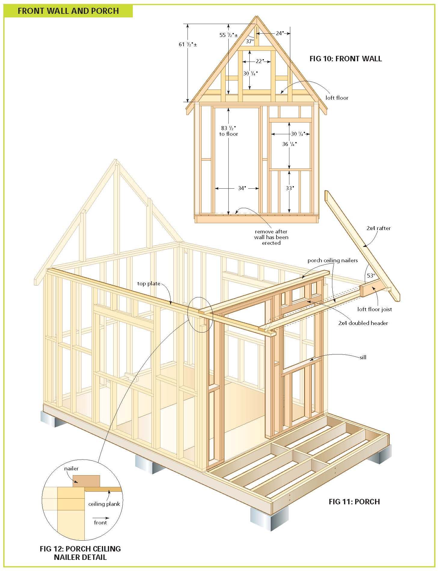
FRONT WALL
1. Cut all front wall pieces to length (see Figure
10). The header over the window consists of two
pieces of 2 x 4 laminated together. Since the front
wall is not a load bearing wall, the header over the
door consists of a single 2 x 4 on the flat to
provide the correct dimension for the entrance door
rough opening.
2. Nail or screw the frame together. Note that the
piece in the bottom plate, where the door is
located, will be removed after the assembled wall is
in place.
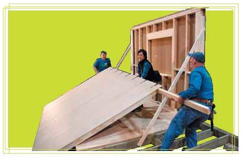
3. Trim two sheets of siding to 91".
4. Lay one panel on the wall over the door opening,
noting that the top edge should be flush to the top
of the double top plate,
|
Free
Wood Cabin Plans
(Right Click on Image, and Select View as
Image or Save As to See the FULL SIZE
Picture)
|
and the
left side should be 3-1⁄2" past the end stud (this
lip will be nailed to the sidewall end stud). Square
everything up and tack the sheet in place. Have a
helper lift the upper end of the wall up off the
floor, high enough so that you can trace the opening
for the door. Lay the wall back down, remove the
sheet and cut out the opening for the door. While
you’re at it, cut out notches for the 6 x 6 side
header and for the rim joists (include the thickness
of the plywood floor in this calculation).
5. Lay the panel back down and nail it to the frame.
6. Lay the other sheet on the frame and nail it
down.
7. Remove the two braces from the side walls and,
with a helper, lift the front wall into place. Nail
or screw the bottom plate to the floor. Nail or
screw the corners together. Nail the 31⁄2" overhangs
to the side wall end studs. (If the floor is level
and the walls are square then, when assembled, the
walls should be plumb.)
8. Before you can cover the porch ceiling, you will
need to scab a 2 x 4 nailer to the top of the front
wall double top plate to act as a nailing edge (see
Figure 11). It should extend about halfway over the
leading edge of the double top plate.
9. With all four walls in place, drive the bottom
plate nails home, cut out the openings for the front
window and door, and then cut out the sill space for
the door opening.
PORCH
I chose cedar for the front porch – despite its
rather steep cost – chiefly because it is hard to
find 6 x 6 pine (my preferred material). PT is a lot
cheaper but far less attractive than cedar, unless
painted or stained.
1. Cut the 5⁄4 x 6 deck boards to length – allowing
for 1" of overhang at the front – and nail or screw
to the joists. A clearance hole may be needed at the
board ends to prevent splitting. Begin in the centre
and work your way out evenly to both sides, leaving
a 3⁄8" gap between the boards. The last two boards
may have to be ripped – make sure to leave a 1"
overhang as well. If you were careful, each end
board should be the same width.
2. Cut the two 6 x 6 porch posts and the front
header to length; the header is mitered at both
ends. (Mitering the 6 x 6 is a bit of challenge if
you do not own a 12" compound sliding miter saw:
Mark your cut line, then take passes with a circular
saw from either side. There will likely still be a
sliver of wood in the middle that you’ll need to
clear with a handsaw.) Drill two 1⁄2" holes, 3⁄4"
deep in the end faces, as in Figure 14.
3. Stand the end posts in place. Lag the 6 x 6 by
431⁄2" side headers to the tops of the posts with
the 8" lag bolts. Plumb the posts and toenail to the
floor, keeping the nails or screws below the line of
the trim (about 2"). For added strength, you can
also drive a few screws up into the post end from
the underside of the deck boards (though it’s a
little tricky, considering that the piers may be in
the way!)
4. Lift the 6 x 6 by 8' front header into place.
Attach it to the side headers with outdoor glue and
the #12 x 31⁄2" screws. Plug the holes (glue the
plugs in place and trim them after the glue dries).
5. Add the 2 x 6 top plate and screw or nail it down
to the front header. Drill a 1" hole about 2" deep
down through the 2 x 6 into the top of each end of
the 8' header . Drill a 5⁄16" clearance hole as in
Figure 16. Lag the 8' header to the end posts. Also
screw the side wall 2 x 4 top plate to the header
using #8 x 3" screws with clearance holes to
minimize splitting.
6. Screw or nail the 2 x 4 nailing edge to the 2 x
6, as in Figure 11.
7. According to our local codes, a deck does not
need a railing if it’s less than 2' above grade. For
decks higher than that, the railing must be no less
than 35" high. If the deck is higher than 5'11"
above grade, then the railing must be 42" high. If
you are installing the optional railing assemblies,
start by notching the newel posts, as in Figure 15.
Determine where the newel posts will be situated and
mark 13⁄4" by 31⁄2" rectangles on the deck boards.
Remove the marked boards and cut out the rectangles
with a jigsaw. Replace the boards, fit the newel
posts into the holes, and clamp in place. Make sure
that, once installed, the railing assembly will fit
tightly against the newel and corner posts. Drill
two 3⁄8" holes through the rim joists and each newel
post. Insert the 3⁄8" x 6" carriage bolts, add the
washers and nuts, and tighten.
8. Cut pickets to length (36" or 38", see below) and
router all four edges with a roundover bit. Screw
the pickets to the handrails. I suggest covering the
screws with 3⁄8"-plugs on the top handrail for a
more attractive finish. Drill pocket holes (with a
pocket-hole jig) slightly angled out on the
underside of the handrail ends and secure them to
the posts. Router the handrail and shoe rail edges,
top and bottom, with a roundover bit. To keep the
pickets from turning, glue them in place.
9. Cut out and assemble the brackets (see Figure
13). Locate and attach to the posts and headers with
eight #8 x 2" screws per bracket. If you’ve plugged
all of your holes so far, then don’t neglect to do
so now (this requires 3⁄8" plugs).
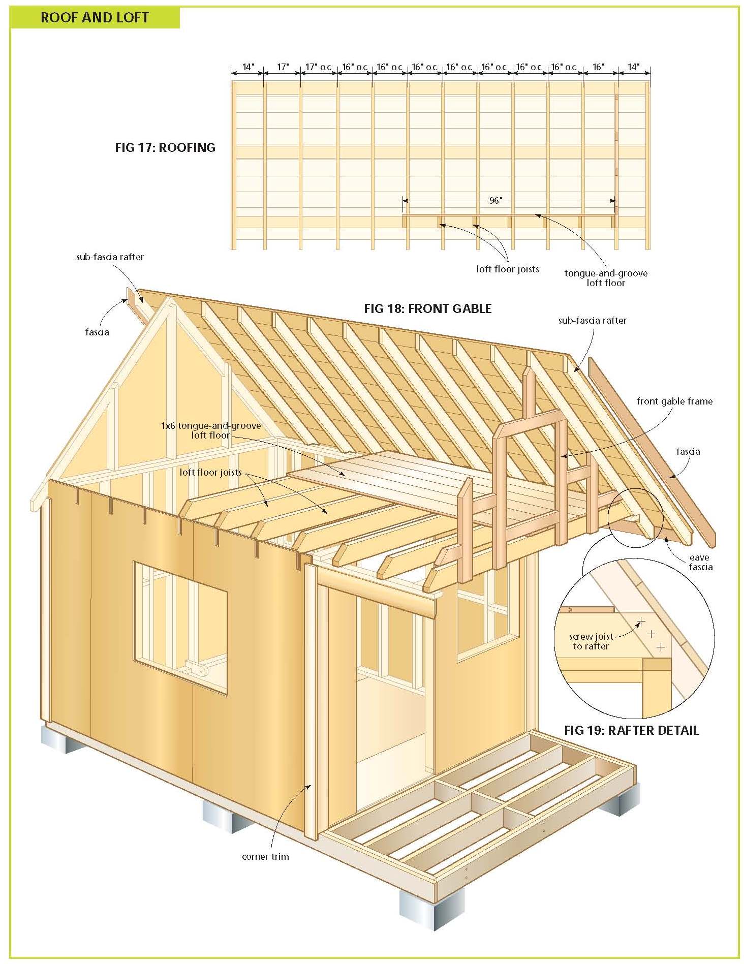
LOFT
The loft joists are located on the inside of the
roof rafters, as in Figure 17. The rafters will be
screwed or nailed to the joist ends later.
1. Cut the loft joists to length and trim the
corners as required. Set the joists in place and
toenail to the top plates.
2. Cut bridging pieces to length and install between
the loft joists, as in the floor construction. The
loft floor, as well as the railing and gate
assembly, can be installed once the rafters have
been installed (see roof instructions).
3. Next, you need to finish off the ceiling of the
porch area with pine tongue-and-groove. Cut the
boards to length and attach to the two nailing
boards and to the underside of the loft joists in
the porch ceiling. You will have to add trim around
the inside perimeter to hide the gap left over the
headers. (The trim is not needed on the front wall,
but makes for a more finished appearance. Add only
after the siding has been installed). This is the
same trim that you will use for the foot of each
corner and newel post.
RAFTERS AND GABLE ENDS
1. Lay out and cut the rafters as in Figures 6 and
7. Note that 22 have a bird’s mouth, while four do
not. Now, 53° might seem like a rather arbitrary
angle for rafters, and it is. It was born out of the
necessity to gain as much room as possible in the
loft and from the fact that my miter saw will cut
angles as great as 65°. So, after a number of
drawings we determined that 53° would give the most
pleasing appearance as well as maximize loft height.
|
Free
Wood Cabin Plans
(Right Click on Image, and Select View as
Image or Save As to See the FULL SIZE
Picture)
|
2. Set
opposing rafters in place on the top plates,
beginning at the porch end. The first seven sets sit
tight to the loft joists (the leftover piece of
plywood laid on the loft joists serves as an
excellent temporary floor). There is no ridge board
in this plan so the rafters will butt up against
each other. Screw or nail the rafters together at
the peak, toenail to the top plate, and nail or
screw to the joist – where applicable.
3. Plumb up the last set of rafters, bracing them
from the inside of the back wall. Temporarily nail
or screw a couple of 1 x 3s to the rafters to hold
them parallel. Check the spacing between the sets
and check that the first set is also plumb and that
the overall distance is 13'6". Make adjustments as
you go.
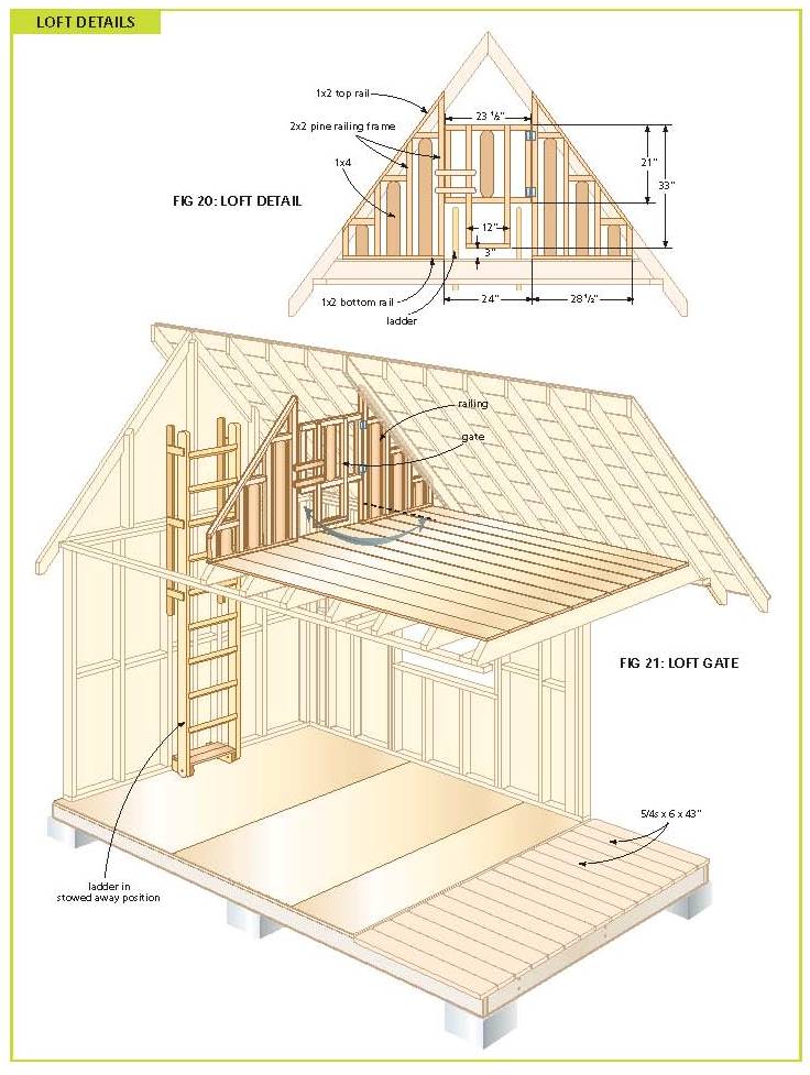
4. Now you can go back and finish off the loft
floor, as well as the railing and gate assembly. For
the pine tongue-and-groove floor, start with the
groove edge of one 96" piece tight to the rafters.
Nail through the tongue diagonally into the joist.
Proceed until you reach the other rafter. Cut short
pieces to fill between rafters and create a seal
between the floor and the roof boards. Nail in place
(it is a good idea to add a nailing strip to the
rafter face as well).
5. Figure 20 shows details for the loft railing and
gate (the view is from the inside of the loft
looking towards the rear of the bunkie). If you plan
to move a large mattress into the loft, hold off on
building this until the end, after you get the
mattress in place. This railing consists of pieces
ripped from lengths of 2 x 4 pine (some retail
outlets sell 2 x 2s) and 1 x 4 boards. There is a
24" gap for a gate in the middle for entry and
egress to the loft via the ladder. The 1 x 2 bottom
rail makes it easy to secure the railing assembly
neatly to the loft floor. The gate swings into the
loft space with two short 1 x 2 pieces acting as
stops. A magnetic catch holds the door closed.
6. Frame the gable ends (Figures 9, 18, and 19). It
is unusual to use 2 x 4s on their faces in the
manner shown in Figure 18 for the front gable, but
it works well in this instance. The gable end with
no window should be framed in the traditional
manner.
7. Side the gable ends. One sheet will do for each;
however, the sheets are too big to handle, so I
suggest doing the layout and cutting on the ground.
Keep in mind that you want the siding to extend 1⁄2"
down onto the 6 x 6 header. You can use the offcuts
from the porch end to fill in the back end, and vice
versa.
8. With a helper working from the loft, lift the
4'-wide, precut centre piece up into place in the
front gable. Tack in place and get your helper to
trace the window opening. Bring the piece back down
and cut out the window opening. Lift the piece back
up into place and nail to the rafters and gable
frame. Nail the end pieces into place.
9. You should also nail filler pieces of siding
between the rafters that sit on the 6 x 6 side wall
headers, bearing in mind that they must be wide
enough to meet the top edge of the rafter and extend
1⁄2" down onto the side-wall headers.
10. You will only be able to add the subfascia
rafters, at the front and back of the roof, once the
roof boards have been nailed in place (Figure 18).
ROOF
1. Starting at the rafter tails and working your way
up, nail the roof boards to the rafters, good side
down, three nails per rafter. The gable overhang
should be 131⁄4" (install long, measure, snap a
chalk line, and cut when the boards are already
nailed down).
2. Screw the sub-fascia rafters to the roofboard
ends.
3. Measure, cut, and nail the eave fascia to the
rafter tails (see Figure 18). The two gable end
tails need to be perfectly vertical.
4. Now cut the pieces for the gable end fascia. In
the middle of two 1 x 6 by 16' boards, make the 37°
cut for where they meet at the peak. Temporarily
tack them in place to the sub-fascia rafters and
trace the line where these meet the eave fascia.
Remove and cut off this piece. Nail to the
sub-fascia rafter and to the eave fascia.
5. Staple the roofing underlayment to the roof
boards, beginning at the bottom.
6. Cut the steel roof panels to length with a
metal-cutting blade in your circular saw. Make sure
you use a straightedge guide.
7. Install the panels with the cut edge towards the
peak, overlapping each panel with the next, by about
1". We used 11⁄2" screws to avoid strapping. (Do not
overtighten as the screw tips will pierce the roof
boards. If any do poke into the loft space, file or
cut off the tips with a mini-grinder.) Rows of
screws should be 2' apart. You will have to overlap
the last panel.
8. Install the ridge cap. You’ll have to cut one of
the ridge cap pieces to length – don’t forget to
leave extra length to allow the pieces to overlap
each other.
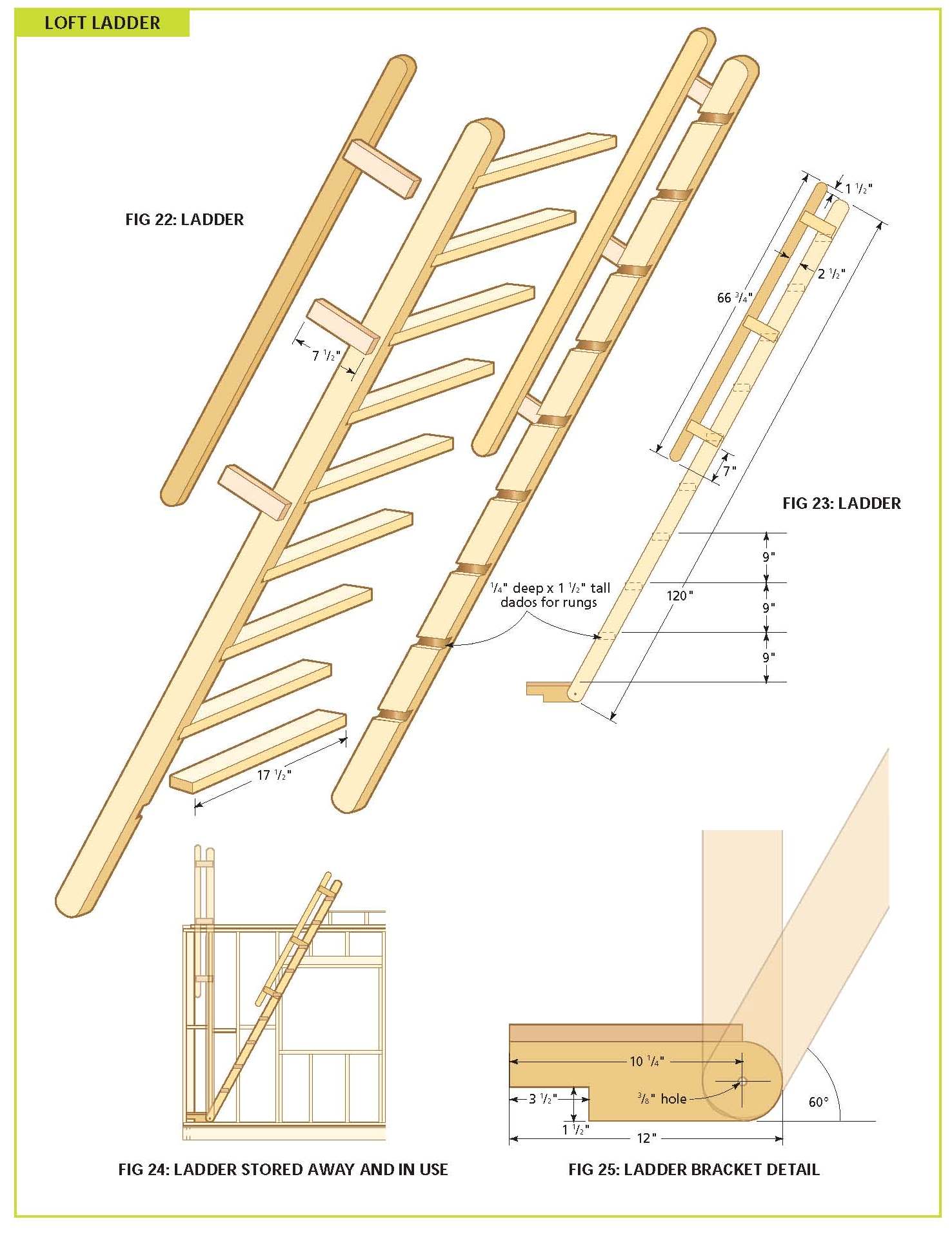
LOFT LADDER
1. Cut the two ladder stringers and brackets to
length from the 12' lengths of 2 x 4 pine (see
Figure 23). The rungs are cut from a 2 x 4 by 14'.
Using a jigsaw, round the ends of the stringers and
the brackets.
|
Free
Wood Cabin Plans
(Right Click on Image, and Select View as
Image or Save As to See the FULL SIZE
Picture)
|
Router
and sand the outside and inside perimeters of the
stringers and rungs with a roundover bit.
2. Lay out the rung pattern on the stringers (the 9"
rise is something of a compromise between a stair
riser – about 8" – and a ladder rung – about 11".
(It also makes the last step 9" below the loft
floor). Remember that the pattern will be opposing.
Cut 1⁄4" by 11⁄2" dados into the stringers to accept
the rungs, as in Figure 22.
3. Drill 3⁄8" holes in the ends of the stringers and
in the ladder brackets where indicated (Figure 25).
4. Assemble the ladder using #9 x 3" screws and wood
glue. (Fill the holes with plugs if you’ve done so
elsewhere.) Make sure construction is square before
the glue sets.
5. Cut handrails and handrail brackets to length as
in Figures 22 and 23. Round the ends of the
handrails and router both inside and outside
perimeters.
6. Secure the handrail brackets by glueing and
screwing them to the outside of the stringers (with
#8 x 2" screws). Glue and screw the handrails to the
inside of the brackets (with #8 x 11⁄4" screws).
7. Set the ladder brackets in place on the inside of
the appropriate studs (Figure 9) and drill two 5⁄16"
holes through each bracket and stud. Fasten the
brackets to the studs with two 5⁄16" x 4" carriage
bolts, washers, and nuts (with the nuts on the
inside). 3⁄8" x 4" carriage bolts, washers, and nuts
(again, with the nuts on the inside).
8. Secure the ladder to the brackets with the 3⁄8" x
4" carriage bolts, washers, and nuts (again, with
the nuts on the inside).
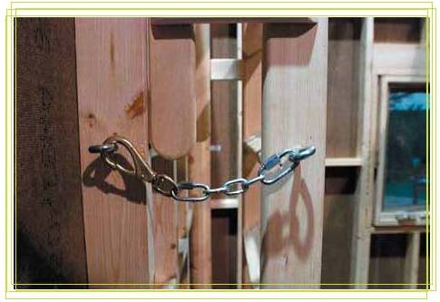
9. Lean the ladder against the wall. Screw a 3⁄8"
eye bolt into the ladder stringer and into a rung (a
pilot hole is essential). At the same level, drill a
3⁄8" hole through the closest stud (see photo,
above). Insert a threaded eye bolt into each hole
and add a washer and nut. (If you need to cut the
bolt to length, file the end smooth.) Use a quick
link to attach one end of the correct length of
chain to the eye bolt in the ladder. Use another
quick link to attach a snap to the other end of the
chain. Snap to the eye bolt in the stud and, voilà,
the ladder is secured. You may have to play with the
chain length until you are satisfied.
10. Unhook the snap and lean the ladder against the
loft. Cut two pieces of pine tongue-and-groove
board: 1" x 6" by 17". Screw or nail to the top of
the brackets (Figure 25). These boards form the
first step. (If screwing, it is a good idea to drill
clearance holes to minimize the risk of splitting.)
The boards should not extend out over the curve of
the brackets.
WINDOWS
We used Anderson windows. I also opted for pine
frames and brick-stop mouldings. In this instance,
because of the flat siding product we used, the
windows can be installed over the siding.
(Generally, windows are installed first and then
siding butts up against the frame.)
1. Set the windows in the spaces provided (this is
usually a two-person job – one holder, one
installer). Shim for plumb and level.
2. Nail or screw into the sill and studs only,
through the shims, and into the 2 x 4 frame. Again,
3⁄8" holes and plugs should be used for appearance
if using screws.
3. Since the windows I have selected come complete
with brick-stop moldings, these can be nailed into
the 2 x 4s as well. (To reduce drafts, you should
caulk around these later with a paintable or colored
caulk.)
4. Carefully trim away the shims. Note: The windows,
door, siding, and roofing materials are all
special-order materials. Allow 2–3 weeks for
delivery.
DOOR
1. If the entrance door you select is prehung
(always the better option), then installation is
straightforward. Remove the pins from the hinges and
lift the door out of the frame. Sit the door frame
in the opening. (Note that you will need to add a
strip of 3⁄8" plywood to the underside of the sill
to bring it level with the deck boards.) Level the
top jamb, shim, and plumb up the hinge-side jamb.
(Shims on the hinge side should be situated behind
the three hinges.) Shim and plumb up the strikeplate
jamb, keeping it parallel to the hingeside jamb.
(Shim in three places as well, making sure to place
one set of shims behind the strike plate.) When you
are satisfied, nail in place. Hook the door back
into the hinges, add the pins, and check that it
operates smoothly. Tip: For a more secure
installation, remove one factory installed screw –
the middle one – from each jamb hinge and substitute
a longer one that will pass through the shims and
well into the 2 x 4 trimmer.
2. Some pre-hung doors come complete with brick-stop
moldings already installed. If not, you will have to
cut and nail the trim to the door jambs.
3. Installing the screen door may require mortising
the hinges. (I recently acquired a $50 mortising jig
for my router and it performed exceedingly well.)
However, the door from Beyond The Screen Door
actually mounts to the brick stop molding, so I used
face-mount screen door spring hinges.
TRIM AND FINISHING
1. Since few places sell cedar trim, you will most
likely have to fashion your own. Rip one 2" strip
and two 11⁄2" strips from the 1 x 6 by 8'. Add a
routered profile of your choice. (Use the same
profile for the porch ceiling trim.) Miter and nail
2" trim around the base of the corner and newel
posts. Repeat below corner brackets as in Figure 14
with the 11⁄2" trim.
2. Trim the inside perimeter of the porch ceiling
with 11⁄2" trim.
3. Measure and trim the 10' length of 1 x 6 pine,
and nail over the sheathing on the rear wall. Centre
it more or less on the line that divides the
sheathing so you can nail into the framing below and
above the top plates. Add a bead of caulk along the
top edge as a water barrier. (To harmonize wood
types, you could expand your budget and select 1 x 6
cedar for the trim instead of pine.)
4. For the corners of the building, we used 1 x 6 to
maintain a balance with the 6 x 6 posts, giving the
structure a kind of faux timber- frame style.
Consequently, one of the two pieces used for each
corner will have to be ripped to 43⁄4".
5. Where the siding meets the roof boards in the
gable ends, trim with 1 x 2.
6. All exterior wood surfaces should be given a
protectant finish.
7. Caulk where required (around the windows, door,
and where the top of the siding meets the rafters
and the roof boards).
|
Free
Wood Cabin Plans
(Right Click on Image, and Select View as
Image or Save As to See the FULL SIZE
Picture)

|
|
Free
Wood Cabin Plans
(Right Click on Image, and Select View as
Image or Save As to See the FULL SIZE
Picture)
|
|
Free
Wood Cabin Plans
(Right Click on Image, and Select View as
Image or Save As to See the FULL SIZE
Picture)

|
|
Free
Wood Cabin Plans
(Right Click on Image, and Select View as
Image or Save As to See the FULL SIZE
Picture)
|
|
Free
Wood Cabin Plans
(Right Click on Image, and Select View as
Image or Save As to See the FULL SIZE
Picture)
|
|
Free
Wood Cabin Plans
(Right Click on Image, and Select View as
Image or Save As to See the FULL SIZE
Picture)
|
|
Free
Wood Cabin Plans
(Right Click on Image, and Select View as
Image or Save As to See the FULL SIZE
Picture)
|
|
Free
Wood Cabin Plans
(Right Click on Image, and Select View as
Image or Save As to See the FULL SIZE
Picture)
|
|